10 Simple Techniques For Mahindra Tree Puller
Table of Contents6 Simple Techniques For Pallet ForksThe Definitive Guide for Shrub PullerAbout Skid Loader Attachments

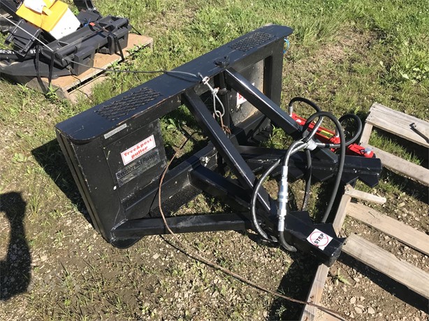
8 is a perspective sight highlighting a tree holding system adjusted to welcome the tree above the point at which it is clutched by the removing means, built based on a changed form of the innovation. DESCRIPTION OF A FAVORED EMBODIMENT The drawings highlight a tree drawing device for attachment to a working car created in accordance with the invention.


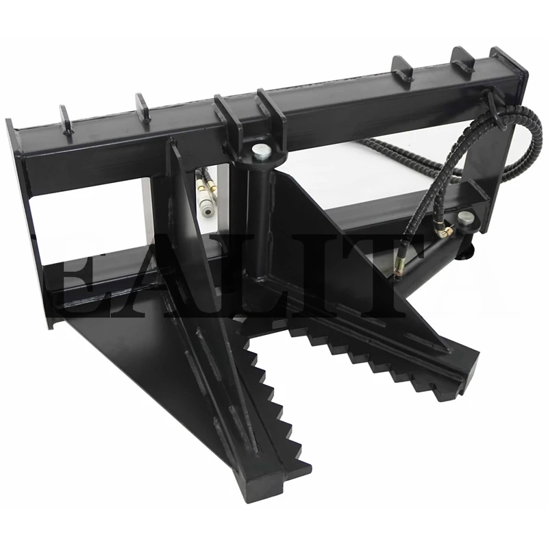
A pair of elongated externally deviating enlarged wedging participants B are integrally signed up with at adjacent ends thereof. A sharpened blade participant C extends inwardly along the wedging participants and also is brought in taken care of relationship thereto. A walk is developed by the blade participants penetrating right into the trunk of the tree forming a complementary ledge in the tree to a level restricted by involvement of internal surfaces of the wedging members with the fibers of the tree trunk.

A taxicab is attended to an operator which includes a front shield participant 13 which may be of increased metal which is adequately supported as at 14 to protect the driver, as well as yet permit the vehicle driver to see therethrough for executing the tree drawing procedure. The common transversely spaced arms 15 are rotated on the framework and also prolong forwardly and downwardly therefrom, while an intermediate section has essential connection as at 16 to the piston rod 17 of a cylinder 18.
The Greatest Guide To Shrub Puller

The piston rod 21 lugged by the piston 19 is pivotally attached as at 22 upon a pair of spaced set framework members 23. The elevatable member A is given in the form of a frame member having substantially rectangular framework supports 24 which specify at the front, an outwardly extending diverging participant 25 forming a notch or V-shaped portion for obtaining a section of the trunk of the tree over the V-shaped gripper.
Installing methods are given for attaching the gripping method B in depending relationship as well as such are highlighted at D. The inwardly projecting blade C is finest shown in FIGS. 2 as well as 6 and also consists of a sharp side 26 and flat blade section 27 which is integrally secured to the enlarged wedging participants B, affording an upwardly expanding wedging surface 28. skid loader tree puller.
The mounting way D consists of pivotal link as at 31, upon spaced mounting plates 32 for accessory to the upright affiliation 33 which has crucial link as at 34 with an ahead section of the elevatable structure participant A. The placing means D is more illustrated as including a compressive assistance structure section 35 which has spaced pivotal links 36 upon the tiltable ground engaging frame add-on F. The footwear see this site 40, preferably have upwardly tapering ends 40a for promoting motion thereof along the ground primary to involvement of the tree as well as actuation of the spaced cyndrical tubes E which vigorously raise the elevatable framework A by applying a pressure between an end portion thereof and also the tiltable framework F.
It should be noted even more that the wedging participants B as well as the complementary inwardly expanding blades C are arcuate as well as taper upwardly from the location of essential add-on at 31 towards a complimentary end as illustrated at 45. FIG (shrub puller). 7 shows an adjusted kind of the development consisting of additions as well as improvements.

5 - New Holland Attachments. While delivering over especially rough terrain the tree in some cases revokes the puller head and comes to be unchecked requiring a lengthy procedure of restoring control as well as later on freeing the tree for personality as the distribution to the preferred location. A holding system or grabber has actually been constructed which consists of a pair of opposed arms 48 and also 49.
The Main Principles Of Pallet Forks
The arms are pivotally continued an installing bracket 50 and opposed ends of the arms 48b and 49b are supplied with appropriate essential link to a double-acting cyndrical tube 51 brought by the the original source mounting brace 50. The placing brace has a bifurcated, rearwardly prolonging assistance 52 which pivotally gets a link 53 which, subsequently, has critical connection as at 54 (FIG. quick attach attachments.


A 2nd parallel link 55, spaced rearwardly of the web link 53 has comparable critical connection to supply a controlled positive activity for the gripper indicates. A cyndrical tube 56 has essential link with the link indicates as well as with the framework A so as to regulate the ahead and also rearward activity helpful resources of the gripper suggests.
7 as opposed to bent as well as have rigid connection by dealt with linkage members 57 as well as 58 which have rigid connection with the wedging members, as well as the lifting frame A. The cyndrical tubes E have crucial connection with the framework An and with the ground engaging structure F. The lifting frame An and the strictly carried wedging participant B have pivotal link as at 59 with a standard 60 which, along with the ground engaging structure F froms a supporting frame.